|
Cross-talk detection by means of EMCExplorer
EMCExplorer can identify interference
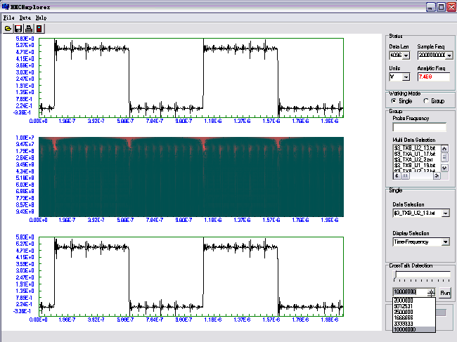
signals caused by cross-talk on PCB. The following steps guide
you through the Cross-talk Identification process:
1. Time-frequency analysis
Choose the signal you want to analyze (for example, data file
named $3_txb_ue_13.txt) and make Time-frequency analysis.
2. Threshold adjustment
From Cross-Talk Detection control panel, adjust the signal
de-noise threshold level by moving track-bar slider. The further
right the track-bar slider is located, the more attenuated the
signal is. This step is optional and the default position of
track-bar slider (the left side) can meet most analysis
requirements.
3. Run cross-talk identification
Clicking the Run button will work out Cross-talk Analysis. The
Results Box (to the left of Run button) shows the frequency of
cross-talk signal (if there was any).
4. Cross-talk identification results
Dropping down the Results Box will show all of the possible
frequencies of cross-talk signal. Because EMCExplorer counts all
possible combinations of periodical pulses, it is possible that the
cross-talk signal with frequency F1 is indicated as F1 Hz, F1/2 Hz,
F1/3 Hz, F1/4 Hz .... Generally speaking, the one among them
with the highest frequency is the real one.
|
